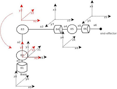
This kinematic diagram looks like the DoIT robot with a very important omission. The DoIT is a 'stacking robot' that preserves the orientation of the spherical wrist (the three last links and the end-effector) when θ1 (Servo-1) is moved.
There's an excellent paper on it here.
For this kinematic diagram to be usable, every time we change θ1, we must change θ2 by the same amount in the opposite direction.
I will be trying to find the Denavit-Hartenberg parameters, but not before I've found all the rotation and displacement matrices. D-H is simpler to use but doesn't offer as much insight.
Let's start by reminding ourselves of the rotation matrices
Now, let's take a long, hard look at that kinematic diagram because there's something wrong with it. The numbering of the angles is supposed to indicate what frame is affected by the rotation. Therefore, the first angle is θ1 because it rotates frame 1. But, there's more:
X2 does not intersect Z1.
To fix this, we renumber the angle and move Frame(2) down so it sits on top of Frame(1).
Now, angles are numbered correctly, and X2 intersects Z1
It might seem weird to just move stuff around like this, but think about it: By moving stuff about, we're changing its location, not its orientation.
We will be affecting the displacement vectors, but not the rotation matrices.
Ponimayet?
The rotation matrix R01 consists of two parts, one due to the way the links are bolted together with the servos in resting position, and one due to the way the servo rotates the joint. We have to dot-multiply them together in order to find the complete rotation matrix for the joint.
We'll take the one with the servos in resting position first.
To find the rotation from Frame(0) to Frame(1), let's see how the axes of Frame(1) are projected onto the axes of Frame(0) and set up a matrix.
The first column shows the projection of X1onto the axes X0, Y0, and Z0, respectively. It is in the same direction as X0, so its projection will be 1.
The other axes (Y0 and Z0) are perpendicular to X1 and so its projections onto them will both be 0. We're done with the first column.
The second column is for Y1. It is in the same direction as Z0, and perpendicular to the two others, so we get
As one might have guessed, the third column is for the Z1 axis.The finished matrix looks like this:
And our complete rotation matrix from 0 to 1 looks like this:

To calculate: Drink coffee. Drink RedBull. This is error-prone and tedious. Thank Zuse we have computers.
Um ... wait. Did I multiply those in the correct order? Nevermind. Let's move on.
Now, we proceed to find R06=R01·R12·R23·R34·R45·R56. Same procedure as above, but this time, I'll try to recap the rules as I go.


No comments:
Post a Comment